|
||
| * * * * * * Cuppa500.com is born * * * * 06-19-2007 * * 04:56 AM | ||
Important Notice to all my readers Due to continual problems with uploading pictures to this site, I have finally decided to quit. However all is not lost, this blog will continue, just not here. All previous entries (between March '06 & June '07) will remain here. Future entries will be on my new website (iWeb) in my own domain. Please click on http://cuppa500.com to visit. Sorry for any inconvenience I look forward to your visits. Please send me an email from the website once you get there to let me know you've been. Thank you for your understanding, regards Cuppa. |
||
| Heavy Recovery *** 05-24-2007 05:29PM *** | ||
A departure from anything related to our bus or travels. We had a little 'excitement' when the cattle truck arrived to take some of my heifers & a bull to market. With someone else's cattle already in the truck, my ones filled it up. Say ? 6 to 8 tonnes, moving around on the back of the tray. Not usually a problem for the experienced driver, until he drops his rear wheel into a ditch he hadn't taken account of, resulting in no drive, & the truck resting on it's fuel tank & toolbox! Completely stuck, not going anywhere! In a desperate moment, the driver cast an eye in the direction of the bus, wondering if I could try pulling him out with it, but grinned before he'd finished his sentence. Just as well 'cos I was laughing out loud at the thought. I think you'll agree that the big tow truck that eventually showed up to pull it out is a beauty. Trucks aren't something I take a lot of notice of usually, but this one was a real pearler with it's immaculate Ned Kelly paint job. Used a winch & cable via a pulley attached to a handy tree. Took longer to decide the best way to do the job than the job itself. Once things were hooked up immense but what seemed like very 'gentle' power pulled the the loaded truck out in about 30 seconds. The truck had been blocking the road for over two hours, but luckily no other vehicles came along. Thankfully the cattle were remarkably quiet & calm, despite being on quite an angle for a while. Guess they're used to it, living on the hills around here! Only damage to the cattle truck were several welds holding the body onto the tray had snapped. Not major & easily re-welded. For those of you with larger motorhomes, you may be interested to know the tow truck's rates were $130 per hour including travel time. Don't think there was an additional 'call out fee. 


regards Cuppa |
||
| * * * * * * Tap Water Supplies * * * 05-24-2007 04:43 PM * * * * | ||
It is apparently not uncommon to find a variety of different taps from which to obtain water supplies from around Australia. Most experienced motorhomers put together a 'tap kit' over a few trips. I have tried to put together a 'universal kit' , but would welcome any suggestions if you think I'm missing something. In Australia there are two commonly sized exterior taps each requiring a different threaded 'click-on' fitting. I can't recall the sizes off the top of my head, (but maybe 3/4" & 1") Whatever they are......most people already have these adapters, which are supplied in all of the cheapie garden spray sets. If purpose buying, brass ones will less prone to breakage. Plastic or brass - I reckon it's worth keeping a few spare 'o' rings tucked away for when the originals inevitably split. Also available are fittings to put onto taps without a thread. These are a thick rubber sleeves with some sort of clamp around them. Push over the spout & tighten. Has a click-on fitting for hose to attach to. There are two sizes available. 15mm & 20mm. 15mm was available off the shelf locally, but 20mm needs to be ordered, which could be suggestive of the fact that if I got one I'd never need it. (Unless you know different? Let me know) 
Then there are the taps that have no handle, requiring a 'key' to turn them on & off. A current discussion on the CMCA's web forum about obtaining these 'keys' brought forth understandable concerns that obtaining these keys & using them amounts to theft of water. In a country suffering widespread drought, water security is on many people's minds. However I believe the sentiment is based upon the mistaken belief that the 'handle-less' taps are designed to prevent water being taken, whereas the taps are sold as 'vandal-proof' or 'tamper proof' & designed to prevent the sort of mini-minded folks who delight in setting off fire extinguishers for fun, doing the same with publicly accessible water taps. Of course having the means to open any tap, does not give the right to do so. Seeking permission first is the order of the day. Any way I bought a selection of 'keys today. As far as I know there five different keys to suit the various vandal proof taps. How common each one is or isn't I have no idea. Luckily the keys are readily available at most plumbing & irrigation suppliers as just one or two tools.  These two are very similar but the brass one is slightly smaller.
  The other three are varying sized splines like this
regards Cuppa |
||
| * * * * * * Water Filtration, Air & More External Storage * * * 05-17-2007 * 04:22 AM * * * * * | ||
The upholsterer has been delayed for a few days, taking longer to obtain the fabric we chose for our cushions than he had expected. In the meantime I've made a couple more additions. Firstly I considered the need for water filtration. Water supplies around Australia are quite variable, with some bore water being less than pleasant in taste & smell. Advice, which struck me as good, from fellow CMCA members is to filter the water BEFORE it goes into our tanks, & then to filter it again between tank & tap for drinking water. Subsequently I bought 3 filter housings that take commonly available 10" filter elements (ensuring replacements are readily available everywhere, unlike some of the 'fancy' filters that require special sized elements at much higher prices). For the 'pre-tank filtration I connected two filters together, the first having a 1 micron sediment filter, the second having a 1 micron carbon silver element. The inlet & outlet have 'click-on' hose fittings. See pics below. 

As you can see in the first pic, the water filler on our bus is pretty basic, no fancy purpose built caravan filler, just a threaded pipe onto which I screw another 'click-on' fitting when filling (& a brass cap when not in use). Many water fillers are not lockable, giving rise to the possibility of unsavoury characters adding goodness knows what into the tanks. Whilst lockable filler caps are available, it seems to me that my set up is 'secure enough', requiring a spanner to remove the brass cap. Carbon silver elements are expensive to buy, but probably cheaper in the long run, as the silver content prevents a build up of bacterial nasties in the filter during periods of non use. I have also connected the airlines to the onboard air compressor, running them to two outlets, one below the front bullbar & one below the rear bumper. This will allow me to carry a much shorter air hose in our storage space. How much use the compressor will get I'm uncertain, but as it came with the bus, it seemed worthwhile fitting it. I expect it to be used when altering tyre pressures on outback unsurfaced roads as well as allowing me to carry a few air tools with us.  Front with 'dust cover' fitted.
  Rear
RearFor storage of 'extra' awning poles (only required if/when we use the zip-on awning walls) & possibly a fishing rod, I made up a PVC storage tube & attached this to the front bullbar.  You may also notice that I've painted the top rear of the bullbar with non reflective matt black paint. I'd found I was getting too much reflected glare from my lights when driving at night. I also 'blacked-out' the inside of the windscreen mesh stone guard & refitted it using stainless screws as the old ones had rusted & were beginning to rust the holes into which they screw. Holes were cleaned & treated with 'cold gal' paint first, & a small dob of silicon put under each screw head, to prevent unwanted ingress of moisture.
Hopefully my next installment will be full of pics of the new upholstery. We are keeping our fingers crossed that our choice of colour will work ok with the existing colour scheme. regards Cuppa | ||
| * * * * * * 2007 Progress - Curtains, Gas & Driving Cabin * * * 04-19-2007 * * 05:22 AM * * * * * | ||
Hi folks, it's been a while since I last wrote an entry here, but never fear progress on the bus has continued, albeit slowly. Like an ostrich burying it's head in the sand, I had tried my best to ignore the water leak from the hot water system, in the hope it would go away. That strategy had clearly failed, when, upon testing the system,after 12 months of 'elective blindness', sure enough a steady stream of water still quickly built to a large puddle under the bus. Time to get down & dirty. What a joy it was to discover the source of the leak was a pipe that had not been pushed fully home into it's fitting. An easy fix. My worst nightmare, that I've carried tucked away in the back of my head for the past year did not come to fruition. If it had been the hot water tank leaking it would have been a disaster. Phew! I have replaced the two kitchen fluorescent lights with a long strip of self adhesive surface mount LED's I bought online from Jaycar. 75 of them. They are mounted under a shelf that is below eye level, so no glare, & they are fantastic. They turn night into day on the kitchen worktop, but better still do much the same in early evening 'half light' when many kitchen activities are likely to occur.  Here are a couple of photos taken in daylight of the light the LED's give. Off
  On
On 
Putting up window furnishings have really helped to start to 'soften up' the interior, (my aim is 'homely & practical'). One of the few things I have salvaged from the vehicle's previous incarnation is the curtains. They are '4 seasons' curtains with a reflective backing to help keep things cool. However I removed the curtains from the driving cabin, & behind the kitchen workspace, giving sufficient excess of curtain material to make some weighted curtains to hang between the driving cabin & house. (This will assist in keeping the cabin cool/warm when driving with the air-con/heater operating). Dividing curtain from 'house  Dividing curtain from cabin
I also made up some pelmets which I covered with the curtain material. It became obvious that pelmets were needed after putting up the curtains.....as a means of keeping out a lot of light that found it's way in over the top of the curtains. Whilst I was at it, I also altered the original curtain rails to allow the curtains to overlap, rather than just pull together. 

In the interests of reducing fire risk, I fitted a roller blind instead of curtains in the kitchen windows. 
The gas stove is now fully fitted, legal & operational, after taking the bus to a licenced gasfitter to have the gas supply connected & issued with a certificate of compliance. The gasfitter insisted I fit a sticker close to the stove warning of the need to restrain combustible materials & raise the pop-up roof! I don't have a pop-up roof. Nevertheless, he showed it to me in his book of gas regulations, so I got one made at a local sign making company. (After checking at a couple of caravan salesyards, neither had ever seen such a sticker). After I had the certificate safely in my possession, I told the gasfitter how silly I felt it was to have a sticker containing instructions irrelevant to my situation. He smiled, agreed, & showed me a number of other 'requirements' he could have insisted upon, stating that the regulations are often a matter of interpretation. Other's experience I've heard of bears this out. It was easier to pay $10 for a sticker than to argue the toss with someone to whom it made no difference if the bus wasn't complianced. 

Driving the 70km round trip to the gasfitters gave me the opportunity to try out the rear vision camera/monitor for the first time. It worked really well, just like a normal rear vision mirror. Makes driving much easier......provided each time the ignition is switched on I remember to push the button to reverse the image. The default image is the opposite of what I want. However I did become aware that I do have a blind spot where I cant see an overtaking car in either the monitor or my side mirrors. An additional convex mirror should sort that. Driving is so much less stressfull if you don't have to guess where your fellow road users are! The bus is booked in at the upholsterers in mid May, to get the seats & other house upholstery made & fitted. Before then we need to get the new mattress, so the upholsterer can work up to it's edges in places. With the upholstery done, construction of the house section of the bus will be complete! Yay!!! Woohoo!! Inside, this leaves the driving cabin, in particular the front 'parcel shelf', instrument panel & dash surround area are a mix of tired looking, unnattractiive brownish hues. All functional, but in need of a spruce up. A few days ago I removed the dash & it's surrounds as much as I could. I was suprised at how little was removable, much of the 'dash' being an integral part of the front structure of the bus, welded into position. Nevertheless, removal of what I could get off was fairly simple, unlike many 'behind the dash' jobs that are a nightmare in many cars. I decided to paint the plastic insrtrument panel. Applied 2 coats of plastic primer, 2 undercoats, 5 or 6 topcoats, plus 2 clear topcoats. After all that I'm still not sure that metallic sherwood green was a good choice. If it just isn't right, I'll probably re-do it in matt black. I was keen to soften up the cabin interior a bit, after all we will be spending a significant amount of time 'lounging' in there when travelling. Repainting the front dash surround' parcel shelf would have succeeded in 'freshening it up' but would have remained 'hard' & subject to getting very hot from the sun. However finding a suitable finish that I could do myself and obtain a pleasing & durable result was not easy to find. The obvious initially seemed to be thin marine type carpet, but after I'd looked at some, I was unable to see how I could 'mould' it around various curves & corners without it looking wrinkled & daggy. It was too thick & lacked stretch. Whilst at the upholsterers I thought I'd found the perfect finish, just the right colour & texture & thin. Unfortunately it was then pointed out to me that I was looking at the rear of the product! - Doh! It was vinyl sheet & the 'back' would not be durable enough for my purpose. Shame! However, after rummaging around in the upholsterer's stock of fabrics I found one that is just about perfect. The colour (dark grey) is what I wanted it's velour with a thin (about 5mm) backing of soft foam. on the back of the foam is a vey thin fabric 'membrane. I wasn't too sure how easy it would be to use, but the upholsterer assured be that with a little care, I'd be able to get a good result. So armed with my wifes best dressmaking scissors, &several aerosols of contact adhesive, I got stuck in. (Actually I went to quite a bit of trouble to ensure that I did not get 'stuck in') to ensure I ended up with a clean finish. The foam is fairly easy to separate from the rear of the fabric, & I used some without foam in places, but kept as much as possible with the foam intact. It is much easier to apply with the foam intact, the foam's compressibility/bounce helps to take up any minor imperfections. I think it turned out pretty good - here's the pics. BEFORE 


AFTER 


I think I may have referred to the need for 'alternative transport' to take with us our big trip. Having realised that it is not possible to legally hang a motorcycle in the back of the bus (it would project past the legal overhang limit), we have decided to tow a small trailer, with two motorcycles. These will allow us to go shopping/exploring atound a locality without breaking camp, as well as allowing exploration areas beyond where the bus can go. At present I am considering a pair of 200cc ag-bikes.They are small, light & comfortable & come with racks that will easily allow for the carriage of extra fuel/water & camping gear for extended trips 'off the beaten track'. However whilst the motor in the bus is low mileage & in fine fettle, it can hardly be described as a a brisk performer. It'll get you there, just not very quickly. Realistic cruising speed on the highway is 80-85kph, with even moderate hills knocking this down very quickly. To get 100kph means constant changing up & down the 10 speed box, not generally worth the effort. So to put a trailer on the back, slowing us down more, with the intention of towing it all around Australia would be an act of masochism ...... some might be able to cope with this......personally I think it would be a constant source of frustration & stress. What to do? Answer: Spend money! Approximately $5000 (!) will get me a turbo kit fitted with a guaranteed power increase of 30% & a torque increase of 40-50%. A company in NSW have a kit designed for my motor (ED33) & are used to working on motorhomes, providing overnight 'camping' facilities for customers. ( http://www.turboglide.com.au/index.cfm?fuseaction=product.display&Product_ID=26 ) We'll probably arrange to call in to get a unit fitted at the beginning of our big trip. That way we'll also have a good immediate idea of what difference the turbo has made, having towed the bikes about 800kms in 'slow mode' to get there. Whilst it is unlikely to increase top speed it should make a significant improvement to hill climbing ability, as well as improved acceleration & hopefully a cruising speed of at least 90 kph with the trailer on. Fuel consumption should remain about the same or possibly improve slightly I still can't decide whether to get the exterior re-painted. The current paint job is 'solid' but a bit on the tatty side. A new coat of paint would really finish things off, but could also be a magnet for the attention of the odd character who thinks they have more right to my belongings than I do. A good paint job may also be a concern when driving along narrow tracks to bush camps, worrying about it getting scratched. There is a spray painter who lives close by with a full spray booth set-up at home. I think I'll see if he would be prepared for me to 'assist' in preparation/masking up etc to lower costs. If the budget can bear it I may then go ahead. If the price is too high, I may keep the paintwork as it is & claim that I; never wanted to re-paint it for all sorts of sensible & practical reasons! I'm also planning on putting some mesh/shade/privacy/ insect screens over some of the windows, following Barry's example ( http://longlucas.bravehost.com/fitout.html at the bottom of the page). Haven't decided on fitting an insect screen door over the bifold entrance door yet. In the past we used one of those long dangly curtains made from multiple plastic strips, hung over the door. It seemed to keep most of the little buzzy things out. If it proves to be insufficient I'll fit a flyscreen door & frame once on the road. 'Til the next time folks regards Cuppa |
||
| * * * * * * Dining Table (pics only) * * * 11-28-2006 * * * 06:58 AM * * * * * | ||


 |
||
| * * * * * * But Wait There's More ...... LED's * * * 11-17-2006 * * 11:58 PM * * * * * | ||

Here's another light I converted yesterday. Originally it had a single dual filament globe in it, a 21w/5w 'brake-light globe. The switch at the bottom of the lamp allows for a bright & less bright setting. To achieve the two light settings with LEDs I simply made two different circuits on one board. One with 30 LEDs & one with 9 LEDs. To connect to the power, I soldered cables into an old brakelight globe, with the glass removed. (Two positive feeds & a single common negative(. After soldering into the globe base, I filled it with car body filler. 


| ||
|
This is the light that fits into the side-bin /external kitchen. The low light setting is used for 'ambience' when sitting outside, the brighter setting will be used when cooking outside. regards Cuppa |
||
| * * * * * * More LED Lighting * * * 11-16-2006 * * * 02:57 PM * * * * * | ||

My plan was to utilise an unused fluorescent light fitting to house an array of 10mm LED's for use as an area light outside under the awning. It would need to be as bright as the fluro or better, with a good spread of light. Why not just use a fluro? Because a) I got enthused about making my own lights & b) because the LEDs use far less battery power & this is a light likely to be left on for hours each night. If you would like to convert your lights to LED operation, but are concerned you don't have the necessary knowledge or skills You can do it! The info is easily available on the web and there's not much you need to know. Bear in mind that this was my first ever solo electrical/soldering project. (You will have read previously that I did convert a couple of other Fluros to LED with the help of BBarry a week or two ago). I now know what things like 'resistors' do, even if I don't know how they do it! I know that an LED is a 'semi-conductor', but still haven't grasped the concept of just what a semiconductor is. None of that stuff really matters anyway. Putting an LED light together is basically very simple, probably not much more difficult than 'painting by numbers'. I decided to fit the maximum number of LEDs that would fit into the fitting. This was 75 x 10mm LEDs. Any more & I couldn't fit the diffuser on. A handy number as it can be divided by 3 exactly. Using LED's on a 12 volt system it is best to connect the LEDs in groups of 3 (in series + to - to + to - to + to -) with a 150 Ohm ,1/4 watt, resistor include in each group of 3. 25 resistors in my lamp. The board was recycled from the masonite like material, which was the original wall lining in the bus. I cut out a shape that would wedge into the fitting, slightly bowed (to assist with spread of light & to hold it in place securely). I then drew a grid to guide me in drilling 75 pairs of 1mm holes 2.5 to 3mm apart. I used the pointy ends of my vernier gauge to mark hole positions before drilling. I then drilled further pairs of larger holes to locate the positive & negative 'rails' ( single strand of copper wire removed from a piece of multi-strand cable) along the two outer edges. Back to the 1mm drill, further pairs of holes to poke tie wire through to locate the 'rails' in place. (Used those little bag ties that come with freezer plastic bags, with the plastic removed). Next is to push the LEDs into their holes (Most were a snug fit, only a couple were a bit loose, not a problem once soldered). I used 3 different colour LEDs Superbright White (Bluish), Warm white (Yellowish) & 'Yellowish White (different yellowish) which gives a more natural & pleasant light than the Superbright Whites alone, albeit at the expense of some brightness. Starting at the negative rail, I folded the negative 'tail' of the first LED over & soldered it to the rail. Next soldered the positive tail to the next LED's negative tail, continuing thus until just the positive tail of the last LED (of the group of 3) remained standing. This was folded down & crossed with one 'tail' of a resistor. The other tail of the resistor is soldered to the positive rail. Clip off the 'excess' sections of 'tail'. I then repeated this a further 24 times. All that was then required was to solder cables (via the switch in the fitting) to the end of each rail & fit into the fitting. I screwed the fitting onto a piece of ply I had cut to size & shape, with a hole for the rear exit of the cable, & another to assist with hanging. That's all there is to it. LEDs have a rating that says how quick you need to be with your soldering (Eg. 5 seconds at 250deg.C). I can't remember what these were rated, but I'm sure I exceeded it a number of times. However they seem to be more tolerant than the rating suggests, as all worked fine when I fired the light up. On an LED the negative 'tail' is the shortest one of the two. Some LEDs have a 'flat' on one side of their base also indicating negative. Doesn't matter which way round a Resistor is fitted. For other configurations/voltages this onlineLED 'Wizard' takes all the headache out of working out layouts & what resistors to use etc. LED Array Wizard I used 14.4volts supply (to allow for when the batteries are being charged - solar &/or alternator) Diode forward voltage is 3.6volts for these 10mm LEDs Forward current is 25 milliamps As for the results, I'm very pleased with the light it gives, (almost as pleased as I was when it all worked when I switched it on the first time) quite acceptable for an awning light without being too 'glary'. I wasn't sure how it would go with the translucent diffuser (which also has small ridges on it's inside) compared to the 'crystal' type. I actually think it's better, at least for 'portable use' as the 'direct glare factor' is reduced, at least with 75 LEDs. The finished lamp draws just 6 watts/ 0.5amp @ 12volts & is brighter than the 12watt/1 amp fluro tube it replaced, together with a comparable spread of light. 
Ok I fibbed slightly above, I left all the resistors until last, only 'cos I was waiting for them to arrive in the mail. Otherwise I would have done it all in the order I said. This is a pic of the rear side of the board with Led's soldered, before I received the resistors. 
And here it is with the resistors fitted. 
The front side. 3 different colours. Only looks like 2, until powered up. 

All Fluro parts except switch were removed. 
The finished light. 
Here is another little 4 LED light I've also made since the awning light above. It runs on 24volts & is fitted inside one of the two 24v ceiling Fluro fittings to direct more light down into the driving cabin. This addition made the difference between being able to read a map at night whilst in the driving/passenger seats, or unsuccessful squinting in semi shadow. There was no specific cabin light.... until now. As the board is attached to a metal bracket, I insulated the rear of the board with a smear of car body filler. Not pretty, but hidden. 

All for now, Regards Cuppa |
||
| * * * * * * Watching My Back & Stuff * * * 11-07-2006 * * 02:16 PM * * * * * | ||


I finally got around to fitting & connecting my rear vision camera system, & am very pleased with it. In particular I'm pleased with the camera's wide angle of view. With the camera mounted in the middle of the back wall, a few inches above the rear window, I can see wider each side than my mirrors allow, as well as everything behind me, up to within about 3 - 4 feet on the ground & high enough to see any low branches etc. It would be easy to tilt the camera down a little more to get closer to the rear bumper, but then an increasing portion of the picture gets taken up with the aircon unit we have sticking out the back. Mounting it lower on to the boot lid made suprisingly little difference to the overall view, but as I'm still considering towing a small trailer, decided to mount it higher. Actually I did mount it to the boot first & was contentedly sitting in my favourite chair relaxing later that evening, when it suddenly occurred to me that I had forgotten to take into account the possibility of the trailer. Would have given a great close up of a couple of bikes following us everywhere! Despite the lateness of the hour & the comfort of my chair, I went out & removed the camera mounting by torchlight, (Petzyl LED head torch - a brilliant bit of gear - good under the bus too - both hands free) which I managed, but wouldn't have done if I'd left it much longer. That Sikaflex adhesive is serious stuff. With the bracket off, & the remaing goo cleaned off with turps, it leaves 5 holes in the bootlid to repair. Bugger! Routing the camera to monitor cable (carries power+audio+video) internally up to the roof from the boot was achieved with all the cable hidden, but connections easily accessible. Even so the 20 metre cable that came with the 'kit' was far more than I needed. Camera is mounted to an external bracket screwed into roof & sealed & made extra secure with sikaflex, with several coats of additional thermashield 'topcoat' over the cable and its grommet entry point (also sealed with sikaflex). All very nice & waterproof. I chose to connect it all so the camera works full-time, as opposed to operating only when reverse gear is selected. It comes on when ignition is turned on, but has it's own power switch. It's default action is to turn on when ignition switch is turned on(acc). The camera is also fitted with LED's that allow it to see at night. (pic becomes black & white at night) Mounted lower on boot lid to showed close up objects, but little else. Any additional illumination helps eg.reversing light. Mounted at roof height the LED's are useless but the camera picks up any light source quite well, so would see vehicle headlights or a guiding torch. However if I were driving at night I think I'd want to turn the monitor off anyway, I'd find it's brightness distracting, (even on it's dimmest settings). Having to once again slither & slide underneath the bus (feeding & securing cable) was made a little easier by the use of some ramps, but laying on my back, working with my arms in the air is tough yakka. Anyone reading this who is contemplating fitting out a bus, I would strongly suggest that unless you have access to a pit or a hoist when you are at the 'seats out/ready to go stage' that you seriously consider taking the floor out if possible. It gives far easier access to install all the 'underbus infrasructure'. It means needing to have a greater degree of foresight right at the beginning, which can feel a bit overwhelming, but it does no harm to run a few cables that may or may not eventually be used. Someone who has recently commenced a fitout in a very thorough (& thoroughly documented) manner is Julian, a member of the CMCA cyber community. His website is well worth a look. CLICK HERE It was reading about his exploits in conjunction with smacking my head on the diff one more time, that made me realise that although removing the floor seems like a lot of extra 'donkey' work early on, it *will* save much work by the time the fitout is completed, as well as making many tasks easier & more enjoyable. Oh one more thing whilst I'm here. Here's a pic of the waste bin I picked up at Bunnings & fitted under the sink. It's a pedal bin, but was easily 'converted' to a 'self opening' bin with a large washer, a length of nylon cord, 2 small eye hooks & 1 small cup hook. There is an inner bin, that can be removed from the outer which is screwed to the floor. The use of the cup hook allows for the nylon cord to be easily detached, to give access to the the 300w inverter behind it. 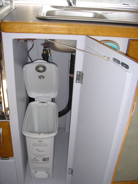
Regards Cuppa |
||
| * * * * * * Table Talk * * * 11-04-2006 * * * 02:32 PM * * * * * | ||
You may recall how I wrote (possibly with a degree of suprise) in an earlier entry, something to the effect the bus is turning out to be a pretty accurate physical representation of the picture in my head, the result of serious amounts time spent 'bus dreaming'. To date I've had to find a few solutions to the unexpected here & there, but basically the layout/design has remained a constant from the outset. Until now! Nothing major you understand, but nevertheless a small deviation from the plan. The plan was to have two swingout/offset tables. One either side of the central aisle, mounted so that they could be used individually, or swung & locked together as one larger table. Both could be swung out of the way easily, an issue with the 'original' table, that constantly needed erecting & dismantling. I bought a couple of lengths of different diameter steel tube, around 45-50mm diameter, with one being a nice sliding fit in the other, & as luck had it the steel merchants had a tube bender, put a 90 degree bend into the smaller (inner) tubes, for no charge. Back home I cut & welded the 'outer' tube to make to table leg holders, with brackets to mount them, & a captive nut with bolt to secure the table leg in use. After cutting the 'inner' pipe to length, to form the leg, I welded a plate to it's bottom, & will place a number of loose small ball bearings in the bottom of each holder, to allow for smoother swivelling. I then cut off the two tapered ends of the original fiamma table leg I had, to use in conjunction with the fiamma alloy 'receiver' s I have. (Screwed onto the underside of the table top). I welded a each cut off conical taper onto the top end of the leg tubes, spending a huge amount of time & caution trying to ensure I got the angles just right. Finally done. Leg holders bolted & screwed into place. With a couple of bit's of scrap MDF to use as temporary table tops, I was almost ecstatic when I brought the two tables together & they lined up beautifully with a couple of slight tweaks. My virtual ecstasy was shattered a short time later when demonstrating the result of my brilliance to my wife., who discovered that if one or both tables was swung & swivelled, & then swung back together again there was a serious mismatch. A result of the tube bending being done 'by eye' & my efforts to get the tapers welded at the correct angles not being good enough. And little I could do about it. At this point I considered as many options as I could in search of a solution. Because I'd always thought the idea of two tables had much merit, I'd not really paid that much attention to the more conventional single table. But when needs must....... Despite the ups & downs of it, I'm so glad the problem arose, because one single table on the swingount leg works really well, it's a pearler! And with a bit of humble pie in my mouth I'll say I think it's actually better than my two table plan. And with a 'leg holder' mounted either side of the aisle, it gives heaps of flexibility as far as table positioning goes. So out with the plan, & in with the revised plan. Frustrating, diasppointing & exciting all at the same time. And I'm only talking tables.....sad isn't it. One of the major benefits of DIY is of course lower cost. "Obvious" you say. "Not necessarily so" says I.. Cost of commercially made chromed swingout/offset table leg = $75 + freight Cost of materials for my two tables = $37 & that included an aerosol of cold galvanising paint/primer & tube bending. Cost of can of aerosol paint, mixed to match our interior $22. (for leg 'holders). Cost to polish & chrome plate *one* table leg $120. !!! Hmmmmmmmm! And it'll be 3 weeks before I get the leg back. . regards Cuppa |
||
HOME :: 1 :: 2 :: 3 :: 4 :: 5 |